
As shown in the figure, the crankshaft flywheel group is mainly composed of crankshaft, flywheel, torsional shock absorber, timing gear (or chain) and belt wheel, etc.
First, the crankshaft
Crankshaft is one of the most important parts in the engine, its function is to withstand the gas pressure from the piston connecting rod group into the torque of the crankshaft and output it. In addition, the crankshaft is also used to drive the valve mechanism of the engine and other auxiliary devices (such as generators, fans, water pumps, power steering pumps, balance shaft mechanism, etc.)
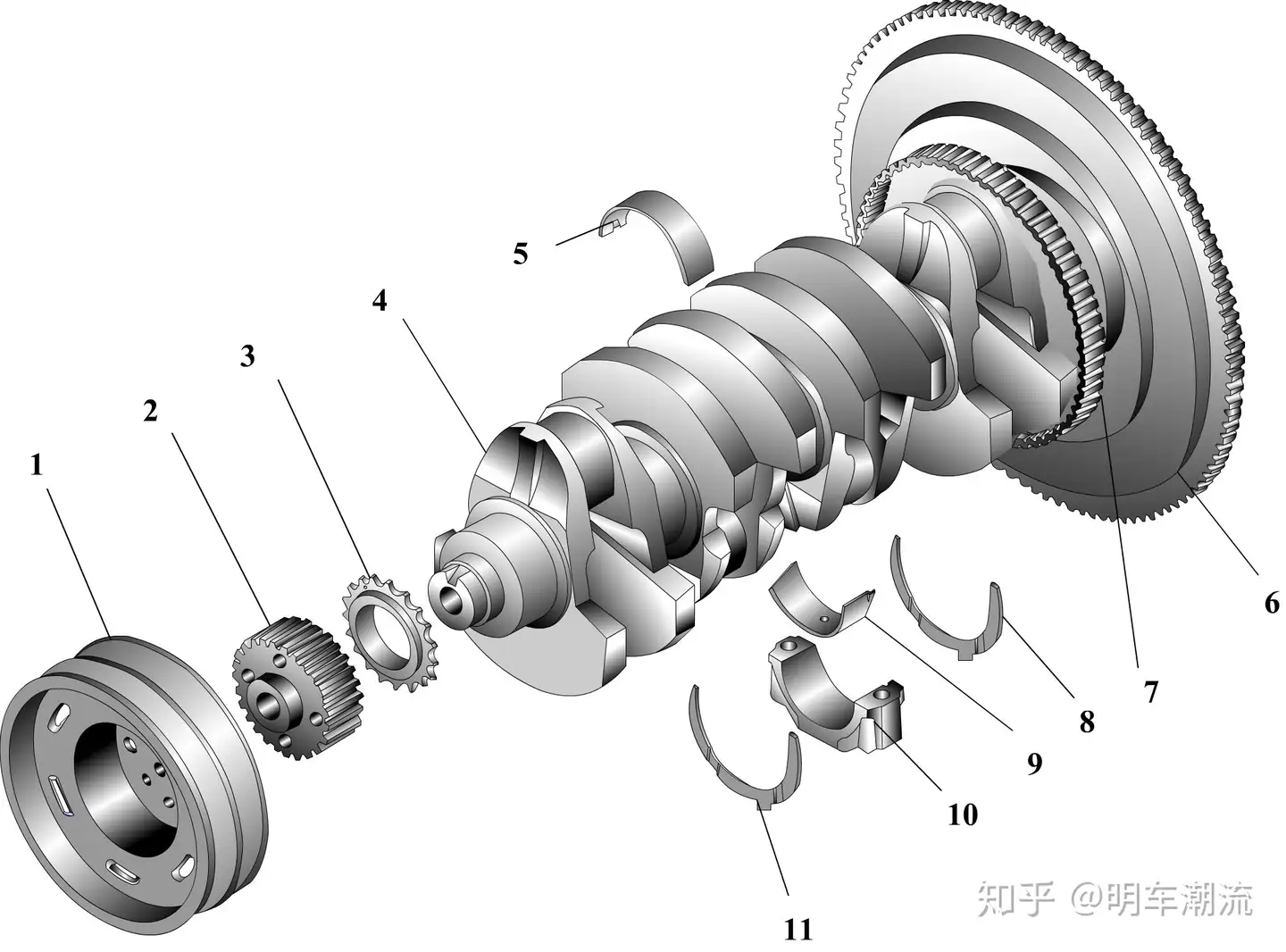
Crankshaft flywheel set
1- Belt pulley; 2- crankshaft timing tooth belt wheel; 3- crankshaft sprocket; 4- crankshaft; 5- crankshaft main bearing (top); 6- flywheel;
7- speed sensor signal generator; 8, 11- thrust pad; 9- crankshaft main bearing (bottom); 10- Crankshaft main bearing cover
Crankshaft work, to withstand periodic changes in gas pressure, reciprocating inertial force and centrifugal force, as well as their high-speed operation under the torque and bending moment, easy to bend and torsional deformation, therefore, the crankshaft should have enough strength and stiffness, good wear resistance and good balance. The crankshaft is generally calcined by medium carbon alloy steel, and the journal surface is treated by high frequency quenching or nitriding. The crankshaft of the Shanghai Santana engine is molded from high quality medium carbon steel. Audi JW and Yuchai YC6105QC engines are cast with low cost and high strength rare earth ductile iron with good wear resistance.
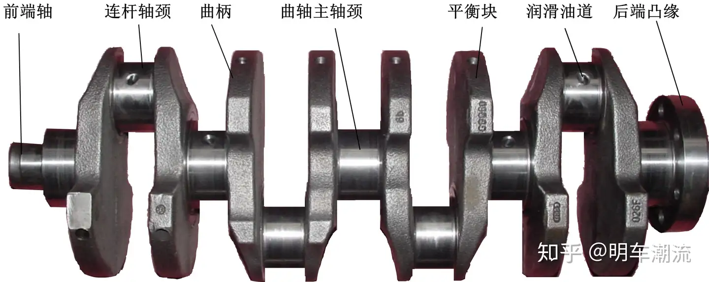
1. Structure of crankshaft
As shown in the figure, a crankshaft is generally composed of a front end, a spindle neck, a crank, a counterweight, a connecting rod journal, and a rear end. A crank consists of a connecting rod journal and its left and right principal journals. The number of turns of a crankshaft depends on the number and arrangement of cylinders. The crankshaft of a single-cylinder engine has only one crank; The number of turns of the crankshaft of an in-line engine is equal to the number of cylinders; The number of turns in the crankshaft of a V engine is equal to half the number of cylinders.
The front end of the crankshaft is equipped with a belt wheel, timing gear, etc., used to drive the water pump, valve mechanism, etc. The spindle neck of the crankshaft is installed in the main bearing seat of the cylinder body and is used to support the crankshaft. The connecting rod journal is used to install the connecting rod. The crank connects the main shaft journal with the connecting rod journal. In order to balance the centrifugal force when the crankshaft rotates, a balance block is provided on the crankshaft. A connecting flange is provided at the back end of the crankshaft to connect the flywheel to the crankshaft by bolts. To lubricate the connecting rod journal, a lubricating oil channel is drilled from the main shaft journal to the connecting rod journal.
Integral crankshaft has the advantages of simple structure, light weight and reliable operation. It generally adopts sliding bearings and is widely used for medium and small engines.
2. Layout principle of crutch
The shape of the crankshaft and the relative position of each crank mainly depend on the number of cylinders, the arrangement of cylinders and the working order of each cylinder. The following rules should be followed as far as possible when arranging the engine working sequence:
Make the two cylinders of continuous work as far apart as possible, in order to reduce the load of the main bearing, to avoid the occurrence of two connected valves opened at the same time in the intake process, the phenomenon of “air grab”, affecting the efficiency of the engine.
The structure of the crankshaft
(1) The working interval Angle of each cylinder should be equal to facilitate the smooth operation of the engine. Within the crankshaft Angle at which the engine completes one working cycle, each cylinder shall be applied once. For a four-stroke engine with the number of cylinders i, the interval Angle is 720°/i. That is, every 720°/i crankshaft rotation should have a cylinder to work, to ensure the smooth operation of the engine.
(2) If it is a V-type engine, the left and right columns of cylinders should alternate work.
3. Common multi-cylinder engine crank arrangement form and working sequence
(1) Layout of crankshaft crank of in-line four-stroke engine
The working interval Angle of the in-line four-cylinder four-stroke engine is 720°/4=180°, and the four turns are arranged in the same plane. The working sequence of the engine (or ignition sequence) is 1-3-4-2 or 1-2-4-3, and its working cycle
Schematic diagram of crank arrangement for an in-line four cylinder four stroke engine
Schematic diagram of crank arrangement for an in-line six – cylinder four – stroke engine
Schematic diagram of the crank arrangement of a V – arranged eight – cylinder engine
Thrust devices commonly used with a single side of the semicircular thrust pad with anti-wear layer, crankshaft main bearing with flanging and circular thrust ring have three forms. The thrust pad is a semi-ring steel sheet with antifriction alloy layer on the outside, which is installed in the groove of the body or the main bearing cover. In order to prevent the rotation of the thrust pad, the thrust pad has a bulge stuck in the groove. Some of the thrust pads use 4 pieces to form two positive circular limits, and some use 2 pieces of limits. The side with the abrading metal should face toward the crankshaft.
Axial positioning of the crankshaft
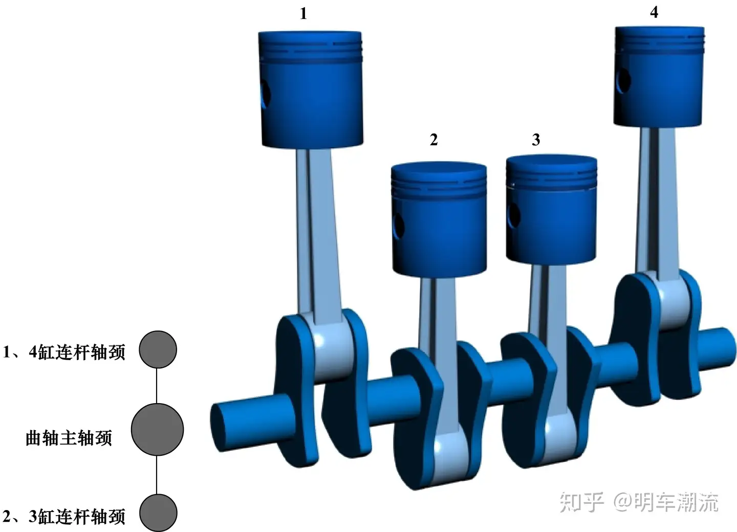
Schematic diagram of crank arrangement for an in-line four cylinder four stroke engine
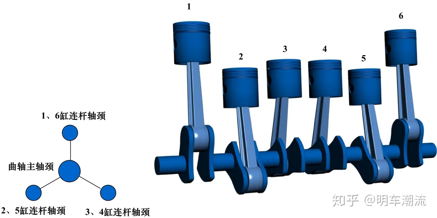
Schematic diagram of crank arrangement for an in-line six – cylinder four – stroke engine
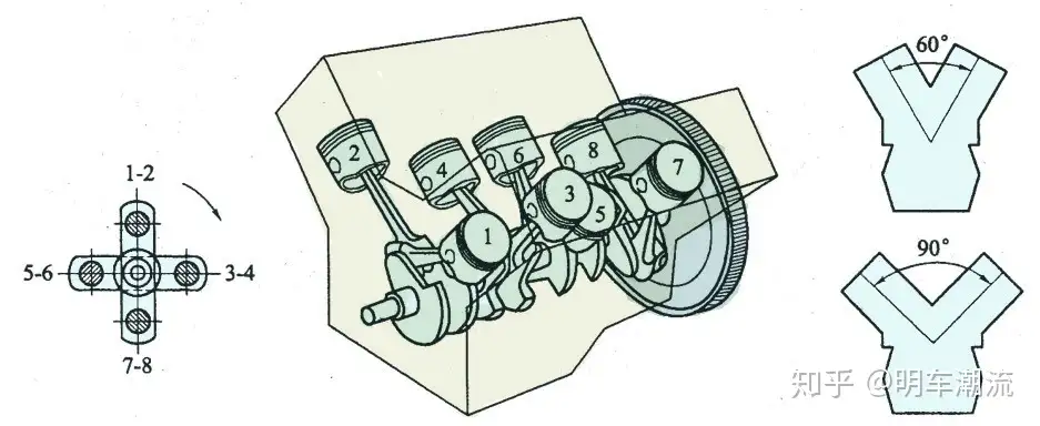
Schematic diagram of the crank arrangement of a V – arranged eight – cylinder engine
Thrust devices commonly used with a single side of the semicircular thrust pad with anti-wear layer, crankshaft main bearing with flanging and circular thrust ring have three forms. The thrust pad is a semi-ring steel sheet with antifriction alloy layer on the outside, which is installed in the groove of the body or the main bearing cover. In order to prevent the rotation of the thrust pad, the thrust pad has a bulge stuck in the groove. Some of the thrust pads use 4 pieces to form two positive circular limits, and some use 2 pieces of limits. The side with the abrading metal should face toward the crankshaft.
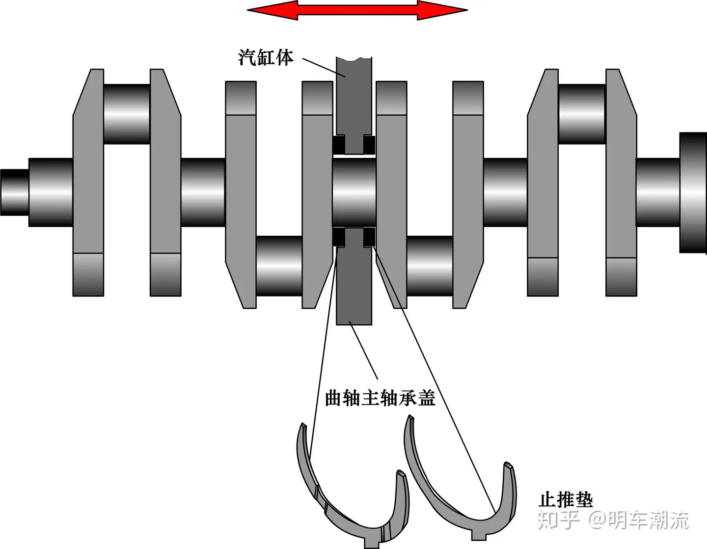
Axial positioning of the crankshaft
Crankshaft main bearing with flanging
The figure shows a crankshaft main bearing with flanging. This bearing is not only coated with anti-friction metal on the cylindrical surface in contact with the crankshaft, but also has anti-friction layer on the flanging edge towards the crankshaft. The bearing is placed in one of the main bearing holes of the crankshaft, and the axial displacement of the crankshaft is limited by flanging.

Crankshaft main bearing with flanging
When the thrust device is placed on the first spindle neck of the crankshaft (the free end of the crankshaft), it may take the form of two thrust rings with antifriction alloy layers. Because it can be directly from the end of the crankshaft into the main shaft neck. To prevent the thrust ring from rotating, the thrust ring is provided with a stop pin hole to match the stop pin on the main bearing cover. When installing thrust ring, steel back should face the body and bearing cover.
